
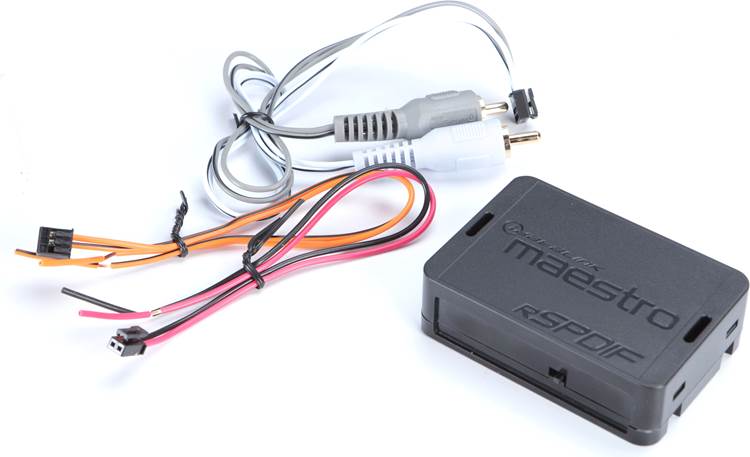

Description
iDatalink Maestro ACC-RR-SPDIF Factory Digital Amplifier Retention Converter
If the new radio is analog but the factory amplifier is still expecting SPDIF, keeping that amplifier takes more than the right plug. The signal format has to be converted.
ACC-RR-SPDIF takes the analog preamp output from a compatible aftermarket radio and converts it to the SPDIF digital signal required by supported factory amplifiers. In a Maestro radio-replacement system, RR or RR2 handles the vehicle integration while ACC-RR-SPDIF handles the audio-format mismatch between the new source unit and the retained digital amplifier.
That can be the right answer when the customer wants a better radio but the factory amplifier is staying. If the build is replacing the OEM amp with aftermarket amplification and DSP, this is usually the wrong architecture—we would use the appropriate amplifier-replacement path instead of converting the new radio back to digital just to feed an amplifier that is being removed.
How It Fits in a Maestro Radio-Replacement System
On a supported application, the aftermarket radio's front RCA preamp outputs feed ACC-RR-SPDIF, the converter creates the digital output the factory amplifier expects, and the vehicle-specific Maestro T-harness carries that signal through the supported factory-amplifier path.
The correct input-level and SPDIF-rate settings come from the radio and vehicle application, not personal preference. The input selector provides 3 V RMS and 5 V RMS settings to match the aftermarket radio's preamp level, while the SPDIF output can be set to 44.1 kHz or 48 kHz to match the factory amplifier.
It Can Also Be Used Outside an RR/RR2 System
iDatalink's installation guide also documents ACC-RR-SPDIF as a standalone analog-to-SPDIF converter with another compatible radio-replacement interface. That does not make it a universal cure for every digital factory amplifier—the factory amp still has to use a supported SPDIF format and the rest of the vehicle integration still has to be handled correctly—but the converter itself is not limited exclusively to RR or RR2.
Opposite Job From ACC-AR-SPDIF
ACC-RR-SPDIF takes aftermarket-radio analog audio and converts it to SPDIF so a supported factory digital amplifier can stay.
ACC-AR-SPDIF is used on the amplifier-replacement side when the factory source is already sending SPDIF and the aftermarket system needs that stream converted to TOSLINK optical or stereo analog.
They solve opposite signal-direction problems. Choosing the correct part starts with deciding whether the factory amplifier is staying or leaving.
Manufacturer Specifications
- Model: ACC-RR-SPDIF
- Product type: Analog-to-SPDIF digital audio converter
- Primary use: Retention of a supported factory digital amplifier during aftermarket radio replacement
- Input: Analog RCA preamp audio from compatible aftermarket radio
- Output: SPDIF digital audio
- Input-level settings: 3 V RMS / 5 V RMS
- SPDIF output settings: 44.1 kHz / 48 kHz
- Maestro use: Compatible RR/RR2 radio-replacement applications where specified
- Additional use: Can be used as a standalone converter with another compatible radio-replacement interface when the application supports the required SPDIF path
Converter only. Maestro RR/RR2, vehicle-specific T-harness, aftermarket radio and other installation accessories are sold separately when used in a Maestro system.
Manufacturer: iDatalink Maestro
Where this fits in the build
This is a system-control or DSP component. The correct choice depends on the signal path, channel count, routing, retained features and the rest of the amplifier and speaker plan.